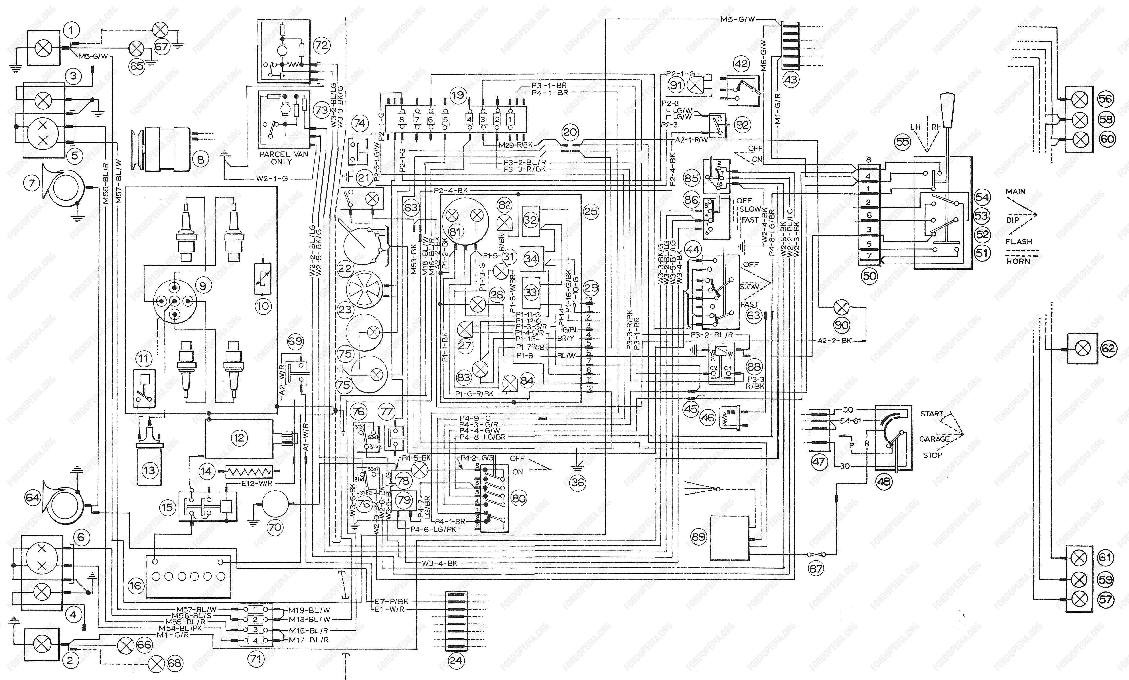
2010 Ford Transit Connect Wiring Diagram Download
- 2011 Ford Transit Fuse Diagram
- Ford Transit Wiring Diagram Download
- 2012 Ford Transit Fuse Diagram
- 2010 Ford Transit Connect Wiring Diagram Download Free

Connected to the recording modules. Ford Motor Company and Ford of Canada do not access event data recorder information without obtaining consent, unless pursuant to court order or where required by law enforcement, other government authorities or other third parties acting with lawful authority. Other parties Introduction 7 2010 Transit. 2010 Ford Transit Connect Electrical Wiring Diagrams Manual. Ford Authorized Manual by Helm, Inc. Detailed wiring schematics, illustrations and component descriptions developed by Ford Motor Company.
Download ford transit mk6 workshop manual - this manual includes all the machine - as well as electrical diagrams,99 ford transit wiring diagram. Transit Ford Workshop Manuals Mechanical Repairs 4 Refer to Wiring Diagrams Section, for schematic and connector. Ford wiring diagram free download - Automotive Wiring Diagram, ECM Wiring Diagram, Electrical Wiring Diagram, and many more programs. Ford transit 2010 model wiring diagram for windscreen washer pump windscreen washer pump failed all of a sudden,if - Ford Transit question. Search Fixya. Jul 17, 2014 2010 Ford Transit Connect. 1 Answer Ford transit 2012 wiring diagram. Go on ford etis website and follow instructions will load wiring diagrams but may need to pay. Sep 06, 2015 This manual is loaded with detailed information on how to service and repair virtually everything on Ford Transit Connect First generation (2009-2012). Indeed, the abovementioned compact panel Van is designed in three different body styles which range from 3-door panel van to 4-door panel van to 5-door MPV.
Radiator Cooling Fan Motor: Diagram Information and Instructions
Introduction
Note
All wiring connections between components are shown exactly as they exist in the vehicles. It is important to realize, however, that no attempt has
been made on the diagrams to represent components and wiring as they physically appear on the vehicle. For example, a 4-foot length of wire is
treated no differently in a diagram from one that is only a few inches long. Furthermore, to aid in understanding electrical (electronic) operation,
wiring inside complicated components has been simplified.
Complete Circuit Operation
Each circuit is shown completely and independently in one set. Other components that are connected to the circuits may not be shown unless they
influence the circuit operation.
Current Flow (1)
Each set normally starts with the component that powers the circuit, such as a fuse or the ignition switch. Current flow is shown from the power source
at the top of the diagram to ground at the bottom of the diagram. A full representation of the power supply of a fuse or the power distribution from a
fuse to various components is given in the Power and Ground Distribution Diagrams. Full representation of the ground connections are shown in the
Power and Ground Distribution Diagrams.
Switch Positions (2)
Within a diagram, all switches, sensors and relays are shown 'at rest' (ignition switch OFF).
Splices (3)
Splices directly connecting to the power distribution are best represented on the power distribution diagram in the Power and Ground Distribution
Diagrams. Splices connected to grounds can be seen completely in the Power and Ground Distribution Diagrams. For all other splices, a reference is
given to each off diagram where that particular splice can be best viewed.
Component Referencing (4)
Components on a diagram have a reference to a component location view or the diagram where it is shown completely. The reference is located to the
right of each component.
Component Names (5)
Component names are placed on the right hand side of each component when possible. Descriptions of the internals of the component are also
included when available. The diagram where the component appears in full is listed in the Index. The base part number for a component is listed in
parentheses next to or under a component.
Internal Name and Function Identification Numbers (6)
Toyota tis keeps asking to download java version. great success with TechStream today. Passenger seat chime disabled; moonroof now opens with windows (both with key in cylinder and holding down button on remote), adjusted rear wiper interval. It works great!
Some components on each diagram have internal symbols with an identification number located within it. You can identify the internal symbol or
function by finding the corresponding number under the component name.
Flat US shipping rate:
2011 Ford Transit Fuse Diagram
$7.95Flat International shipping rate:
Ford Transit Wiring Diagram Download
$22.75Description
2012 Ford Transit Fuse Diagram
2010 Ford Transit Connect Electrical Wiring Diagrams Manual. ORIGINAL. Ford Authorized Manual by Helm, Inc.
Detailed wiring schematics, illustrations and component descriptions developed by Ford Motor Company. Information contained in each vehicle specific manual, has been developed to aid technicians in diagnosing and repairing vehicle wiring and electrical systems. Each manual covers the entire vehicle bumper to bumper including connectors, splices, grounds and component location and testing.
Years/Models Covered
2010 / Transit Connect
Keywords: 1st Generation, Van, Wagon, Panel, Ecoboost
Condition: What you see pictured is what you get. Fresh from a Ford Dealership. Small missing piece from cover by one of the hole punched holes, but light use in the shop, if any. Wiring Diagrams are used in Dealership Shops, Independent Garages and in Fleet Environments and thus can reflect such use, most often showing extensive signs of soiling you aren't seeing here.